SNES Mod - GPIO - Controller + Start/Stop, Reset und LED
-
Hi !
I'm sorry to reply in english, but i think i vae valuable information for you, and my german is ok to read an dunderstand you, but not to answer you.
So, here is the situation as of today :
- mausberry is supported https://github.com/recalbox/recalbox-os/wiki/Mausberry-Switch-Power-On-off-(EN)
- power on/off/reset and led are supported through GPIO https://github.com/recalbox/recalbox-os/wiki/Add-a-start-stop-button-to-your-recalbox-(EN)
- most adatpers SNES -> USB should be supported
- you can use the gamecon driver if you want to map your original SNES controllers without using any USB converter. You need to read the doc and do the right wiring on GPIO https://github.com/recalbox/recalbox-os/wiki/Gamecon-controllers-(EN) (dunno if this has been translated to German, you can still check)
I'm not sure i understood correctly the MCP23017 part ... What i can say is that it is supposed to work but I don't know if the module we compile on Recalbox has this feature. I think it does have it, should ask @digitalLumberjack. I haven't checked either if you can use both MCP23017 with gamecon.
Hope i could be of any help
")
-
Klar hast du genug gpios.
Beim Raspberry 3 musst du für die 2 Controller GPIO 10 = Clock ( zu beiden Controller) / GPIO 11 = Latch (zu beiden Controller) / GPIO 4 = Data 1( Controller 1) und GPIO 7 = Data2 (Controller 2)
GPIO 2 und GPIO 3 sind für deine Power und Reset Button.
Ich habe so selbst 2 NES Controller und den Reset Button realisiert.
Gruß
Jens -
@faxesystem Tolles Projekt. Ich habe etwas ähnliches mit einem defekten N64 gemacht. Siehe meine Signatur
Ich kann dir etwas erzählen wie ich es gemacht habe oder wie du es machen könntest, nur so als Anregung:
-
Ich habe den originalen Ein-Aus Schalter benutzt um die Spannungsversorgung zum RPi zu kappen. Herunterfahren tue ich über das ES Menü.
-
Der originale Reset Button benutze ich um NUR das jeweilige Spiel zu resetten. Das finde ich liegt näher beim Original als das gesamte RPi zu resetten
-
Wenn du die originalen Controller benutzen willst, dann kannst du wie @Substring vorgeschlagen hat die Gamecon Controller benutzen, ohne USB Konverter: https://github.com/recalbox/recalbox-os/wiki/Gamecon-controllers-(EN)
Ein Adapter braucht mehr Platz und es ist meiner Meinung nach mehr Gebastel -
Die Power LED würde ich ganz normal nach dem Wiki das du gepostet hast anschliessen. Ich habe ein Arduino verwendet, da ich das Logo und LED mit RGB gemacht habe
-
Ich denke mit den Gamecon Controller hast du genug GPIO um es ohne Mausberry zu machen (Wären auch wieder mehr Teile sowie kostet es mehr)
Halte uns doch auf dem Laufenden wie dein Projekt vorangeht
-
-
Vielen Dank für eure Hinweise zum GameCon Treiber.
Dadurch kann ich ja direkt auf das Controller PCB vom SNES gehen bzw. das Kabel vom Controller PCB direkt mitnutzen. Ich habe dazu folgende Skizze gefunden  und werde am Wochenende mal löten.
 ") Anbei noch der "tote" SNES links und mein treuer, funktionierender Begleiter seit 1993.
Anbei noch der "tote" SNES links und mein treuer, funktionierender Begleiter seit 1993. 
-
Das ist mein aktuelles Projekt wo die NES Ports und der Resetknopf direkt über die Gpios abgefragt wird.
Zu der Beschreibung von mir oben.
Ich würde gucken ob man auf dem pcb von snes die leiterbahnen zu den Ports unterbricht und dann neu verkabelt.
Weil bei den NES Ports waren zusätzlich zum Port noch Dioden verlötet welche man ja nicht benötigt.
-
Nachtrag: du kannst auch die 3,3v vom Pi benutzen. Das steht auch so im Wiki.
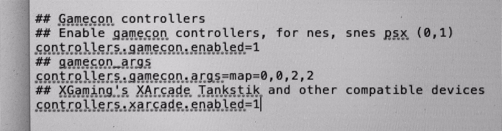
Die Recalbox.conf muss du dann so ändern. Nur wo ich 0,0,2,2 habe musst du den Wert für snes Controller eintragen. Die "2" steht für nes Controller
-
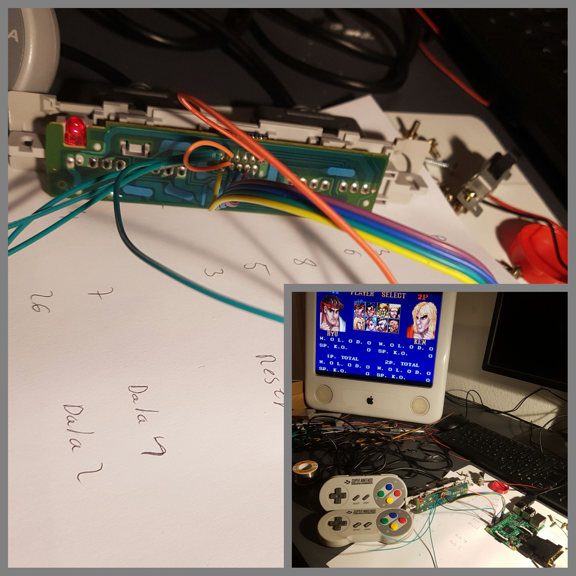
Das war leichter als angenommen. Wenn man direkt das PCB mitnimmt und GPIO 14 als 3.3 Power nutzt läuft sogar die Original LED wie gewünscht.
 Morgen ist dann Dremelarbeit am Gehäuse angesagt und dann war es das schon fast. Ich werde noch einen netten Guide erstellen damit alle was davon haben.
Beste Grüße,
Faxe
-
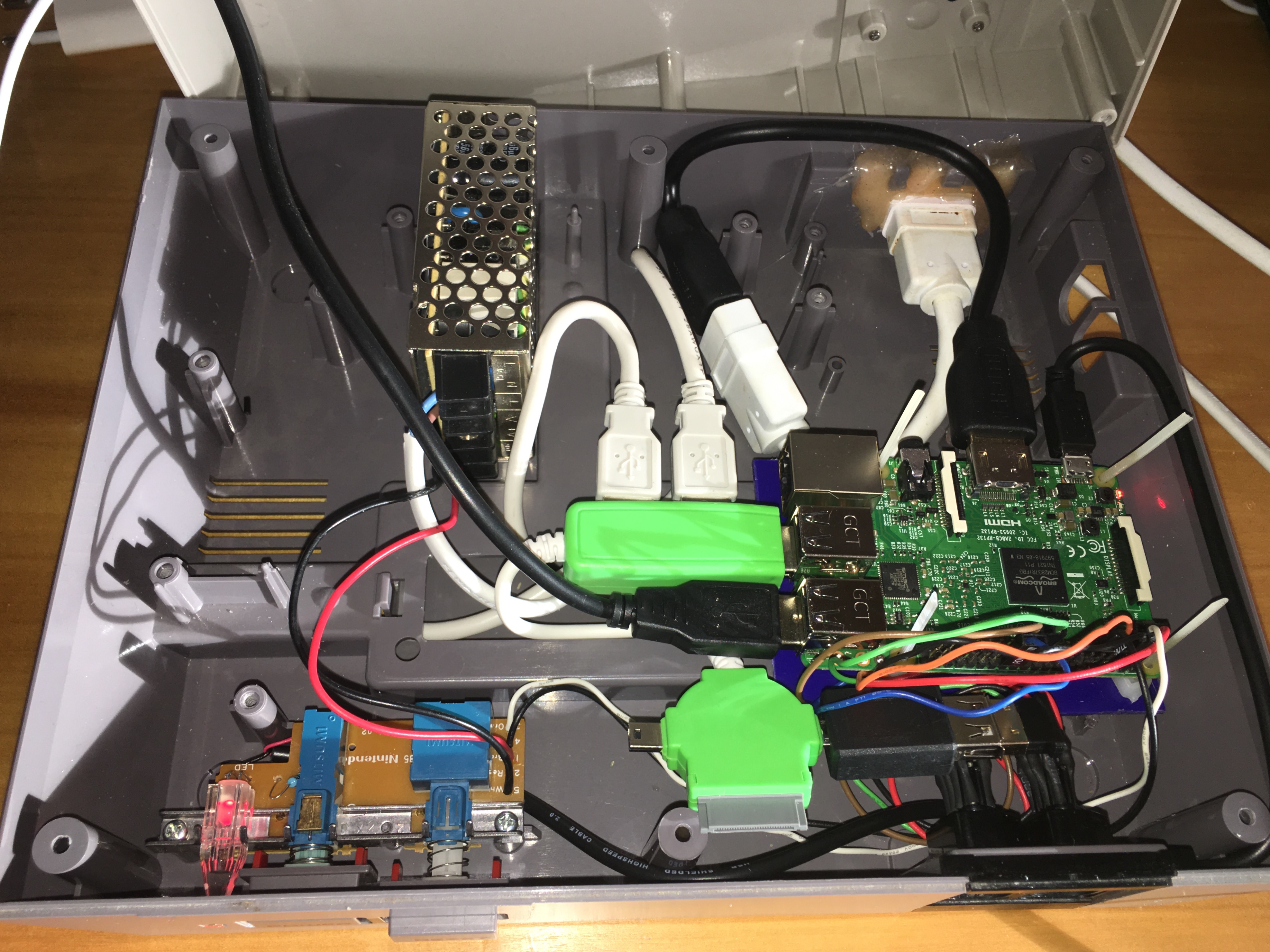
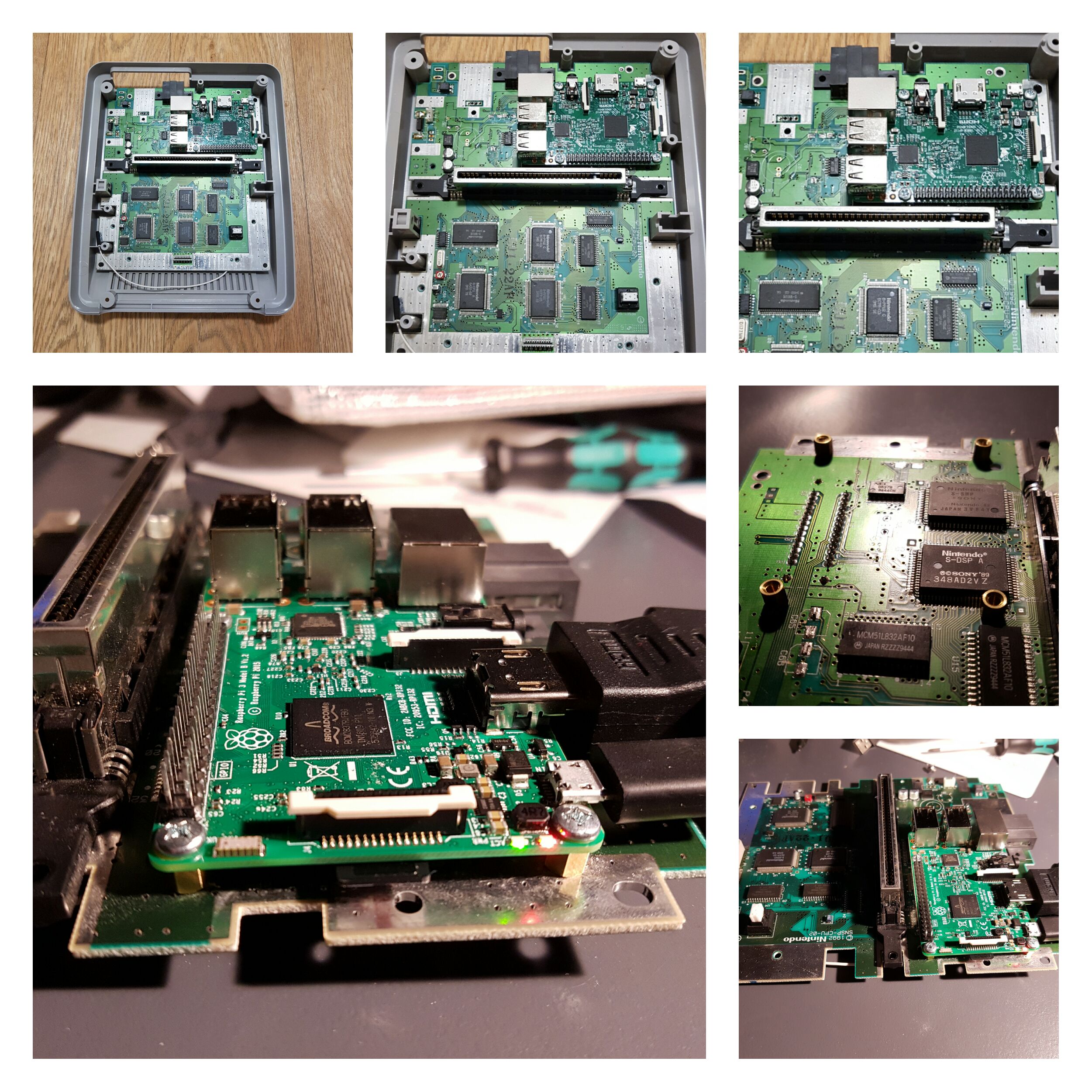
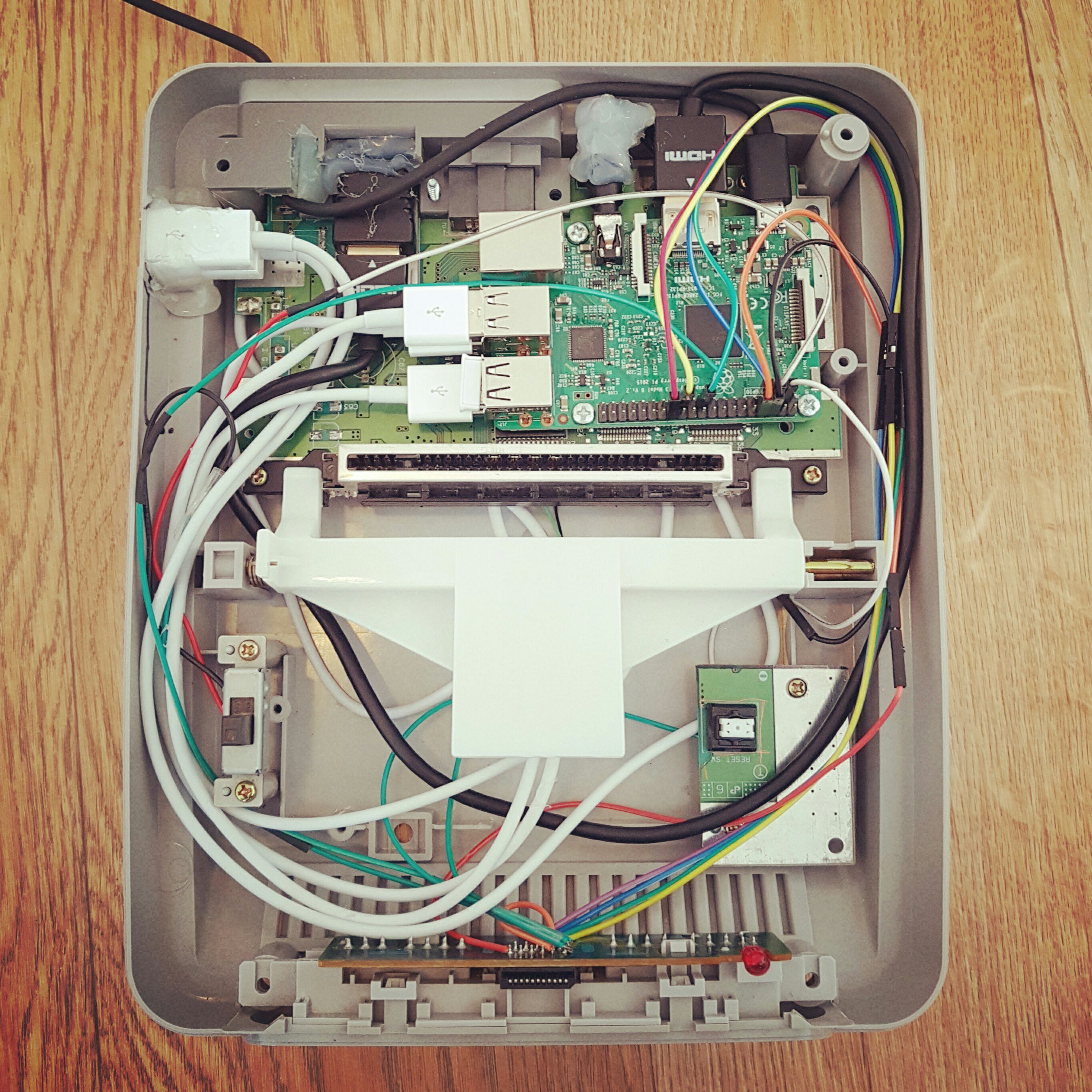
Ich warte leider noch auf Kabel ohne die ich keine Passprobe für das Dremeln machen kann. Aber immerhin habe ich den Raspberry mit dem SNES PCB vermählt.
-
Ich bin fertig. Es war teilweise ganz schön eng aber irgendwie habe ich alles hineinquetschen können. Ich habe noch den Composite Out vom Pi an den Multiout vom SNES gelötet damit er auch an einer Röhre laufen kann. Ebenfalls habe ich 4 Pins vom Cartridge Slot an ein USB Kabel gelötet um demnächst einen USB Stick in eine Cartridge zu stecken ;). Vielen Dank für eure Tipps.
Beste Grüße,
Faxe
-
Gibt es die Anleitung zu deinem MOD schon? Mir gefällt deine Variante.
