Recalbox Forum

    • Register
    • Login
    • Search
    • Recent
    • Tags
    • recalbox.com
    • Gitlab repository
    • Documentation
    • Discord

    Rocker switch on GPIO pins?

    Recalbox General
    rocker switch gpio pins
    4
    17
    6514
    Loading More Posts
    • Oldest to Newest
    • Newest to Oldest
    • Most Votes
    Reply
    • Reply as topic
    Log in to reply
    This topic has been deleted. Only users with topic management privileges can see it.
    • NoAttitude
      NoAttitude last edited by

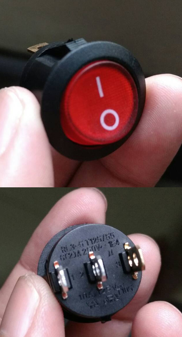
      Is it possible to use this 3 pins rocker switch with LED light on the GPIO pins??

      0_1479897143052_2.jpg

      If it s possible, how am I suppose to wire it ?? I m a super newbie on this. Can you guys help me draw out a simple diagram on how to wire this to my pi ??

      I ve read this link https://github.com/recalbox/recalbox-os/wiki/Add-a-start-stop-button-to-your-recalbox-(EN) but it does nt mention anything on this 3 pins rocker

      Thankyou so much 🙂

      Substring 1 Reply Last reply Reply Quote 0
      • Substring
        Substring @NoAttitude last edited by

        @NoAttitude You should explain how to wire your switch if you want some help. What are the 3 pins used for ?

        Former dev - Please reply with @substring so that i am notified when you answer me
        Ex dev - Merci de me répondre en utilisant @substring pour que je sois notifé

        NoAttitude 1 Reply Last reply Reply Quote 0
        • NoAttitude
          NoAttitude @Substring last edited by

          @Substring it s for the on and off switch.. thankyou 🙂

          Substring 1 Reply Last reply Reply Quote 0
          • Substring
            Substring @NoAttitude last edited by

            @NoAttitude Then how is it lit ? The powerswitch won't send any voltage/current because the detection is made with the GPIO sent to ground.

            So i'm still wondering the meaning of those 1 2 3 pins

            Former dev - Please reply with @substring so that i am notified when you answer me
            Ex dev - Merci de me répondre en utilisant @substring pour que je sois notifé

            voljega 1 Reply Last reply Reply Quote 0
            • voljega
              voljega Banned @Substring last edited by

              @Substring one for ground, one for I, one for 0 si you can conbect your switch as closed on either 0 or I

              NoAttitude 1 Reply Last reply Reply Quote 0
              • NoAttitude
                NoAttitude @voljega last edited by

                @voljega said in Rocker switch on GPIO pins?:

                @Substring one for ground, one for I, one for 0 si you can conbect your switch as closed on either 0 or I

                Do u mind drawing a simple diagram for me ?? T---T I m so confused right now

                voljega 1 Reply Last reply Reply Quote 0
                • voljega
                  voljega Banned @NoAttitude last edited by

                  @NoAttitude just connect the gpio ground to the midde one on the switch, and the other gpio pin on the one under the I on the switch

                  For the gpio pins to use just look on the wiki, tgere's a page on that

                  NoAttitude 1 Reply Last reply Reply Quote 0
                  • NoAttitude
                    NoAttitude @voljega last edited by

                    @voljega 0_1479908604101_Untitled-3.jpg

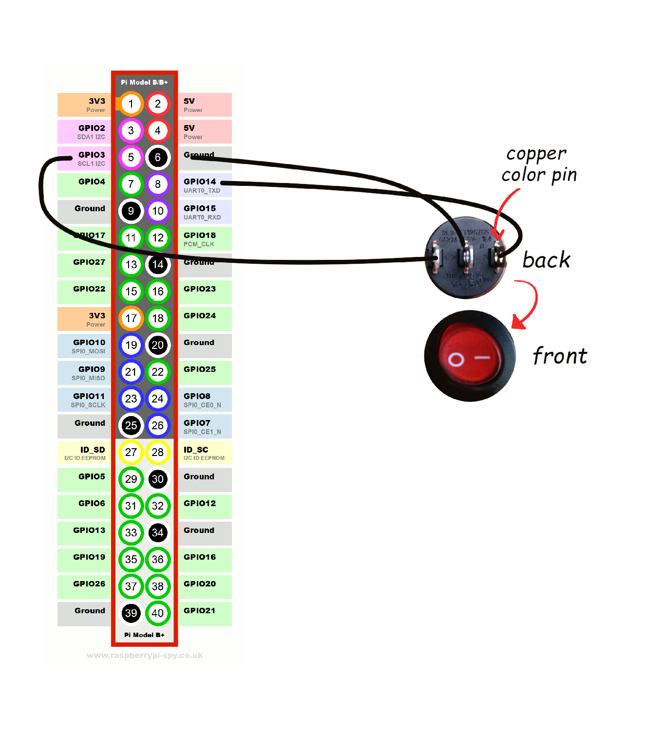
                    Is this drawing method correct??

                    voljega 1 Reply Last reply Reply Quote 0
                    • voljega
                      voljega Banned @NoAttitude last edited by

                      @NoAttitude no as I said pin5 goes on switch I and nothing on switch 0

                      NoAttitude 1 Reply Last reply Reply Quote 0
                      • NoAttitude
                        NoAttitude @voljega last edited by

                        @voljega said in Rocker switch on GPIO pins?:

                        @NoAttitude no as I said pin5 goes on switch I and nothing on switch 0

                        0_1479910412999_Untitled-3.jpg
                        This is it??

                        voljega 1 Reply Last reply Reply Quote 0
                        • voljega
                          voljega Banned @NoAttitude last edited by

                          @NoAttitude that's not what I wrote.

                          NoAttitude 1 Reply Last reply Reply Quote 0
                          • NoAttitude
                            NoAttitude @voljega last edited by NoAttitude

                            @voljega

                            I must be confused here. You said "pin 5" (GPIO3) goes on switch " I " ( Right pin on the switch ) and nothing on switch " 0 " (Left pin on the switch ) Which part I am missing here ?? Thankyou

                            voljega 1 Reply Last reply Reply Quote 0
                            • voljega
                              voljega Banned @NoAttitude last edited by

                              @NoAttitude I never mentioned pin 8

                              1 Reply Last reply Reply Quote 0
                              • NoAttitude
                                NoAttitude last edited by

                                0_1479918157318_Untitled-3.jpg
                                I hope I am correct this time... 🙂

                                1 Reply Last reply Reply Quote 0
                                • voljega
                                  voljega Banned last edited by

                                  I hope so too, you need to test 🙂

                                  NoAttitude 1 Reply Last reply Reply Quote 0
                                  • NoAttitude
                                    NoAttitude @voljega last edited by

                                    @voljega No .. it does nt work T-T

                                    1 Reply Last reply Reply Quote 0
                                    • paradadf
                                      paradadf Staff last edited by

                                      just activate the system.power.switch=PIN56ONOFF and, with cables connected to Pin5 and Pin6, play with the different combinations on the real switch until you find what is right.

                                      If your question was answered, please mark it as solved: Topic Tools -> Ask a question + Topic Tools -> Mark as Solved

                                      1 Reply Last reply Reply Quote 0
                                      • First post
                                        Last post

                                      Want to support us ?

                                      111
                                      Online

                                      98.7k
                                      Users

                                      28.1k
                                      Topics

                                      187.1k
                                      Posts

                                      Copyright © 2021 recalbox.com