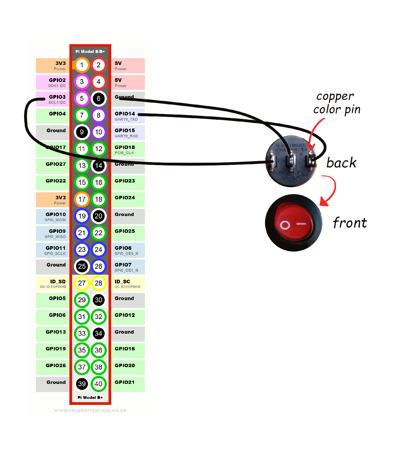
Rocker switch on GPIO pins?
-
@NoAttitude just connect the gpio ground to the midde one on the switch, and the other gpio pin on the one under the I on the switch
For the gpio pins to use just look on the wiki, tgere's a page on that
-
Is this drawing method correct??
-
@NoAttitude no as I said pin5 goes on switch I and nothing on switch 0
-
@voljega said in Rocker switch on GPIO pins?:
@NoAttitude no as I said pin5 goes on switch I and nothing on switch 0

This is it?? -
@NoAttitude that's not what I wrote.
-
I must be confused here. You said "pin 5" (GPIO3) goes on switch " I " ( Right pin on the switch ) and nothing on switch " 0 " (Left pin on the switch ) Which part I am missing here ?? Thankyou
-
@NoAttitude I never mentioned pin 8
-

I hope I am correct this time...
-
I hope so too, you need to test

-
@voljega No .. it does nt work T-T
-
just activate the
system.power.switch=PIN56ONOFFand, with cables connected to Pin5 and Pin6, play with the different combinations on the real switch until you find what is right.

