Recalbox Forum

    • Register
    • Login
    • Search
    • Recent
    • Tags
    • recalbox.com
    • Gitlab repository
    • Documentation
    • Discord
    1. Home
    2. Duds_O_Cara
    3. Posts
    • Profile
    • Following 0
    • Followers 0
    • Topics 2
    • Posts 13
    • Best 7
    • Controversial 0
    • Groups 0

    Posts made by Duds_O_Cara

    • RE: Problema na maneta do arcade

      @Zing said in Problema na maneta do arcade:

      @MrBilly provavelmente o problema é físico.

      Só pra complementar. Já tive uma placa zero delay com esse mesmo problema e era físico. Como tinha mais “conectores” sobrando na placa eu apenas troquei o plug de lugar para um dos conectores não utilizados e deu certo.

      posted in Controles / GPIO / Codificador USB
      Duds_O_Cara
      Duds_O_Cara
    • RE: SD/PENDRIVE

      Acho que sim, qual é o hardware?
      Quando eu usava um notebook dedicado para o recalbox era por meio de pendrive.

      posted in Recalbox geral
      Duds_O_Cara
      Duds_O_Cara
    • RE: Home Button Project

      @redblueflame said in Home Button Project:

      Also @Duds_O_Cara, I think you can use transistors to remove the "switching" noise, typical on relays.

      Yeah, it's really possible! In fact, a few cents cheaper since transistors are cheaper than relays. In my case, I used some relays that I bought for my IoT testing and an old PNP Transistor. It's also possible do it using mosfet or other components "key-like".

      But I'll tell you: I love the relay noise 🙂 ❤ (in fact, when I build my pinball machine I'll use as many as possible of the most louder relays in order to recreate the old school sounds).

      I think a cheap shematic using transistors only should look like this:

      Botao-Home-Mamute-Transistor-600x400.png

      I used tinkercad to validate:
      https://www.tinkercad.com/things/jKHnLiFRhBV

      In fact if I'd build it to myself I think I should add a third transistor and pull it's base source feeding from the Raspberry 5V source trying to isolate the Home Button circuit from the GPIO pin ciruit, like I did with the relay project, so the GPIO pins wouldn't be in charge of operating the transistors. That would be something like this:

      Botao-Home-Mamute-3-Transistor-600x400.png

      Tinkercad validation:
      https://www.tinkercad.com/things/0MSJcpwArDV

      But I cannot grant it's working with the real Raspberry since I don't have any transistors here to mount a breadboard right now. Maybe I could try this one day.

      What do you think about this schematic? Would this run along with Raspberry?

      posted in Community projects
      Duds_O_Cara
      Duds_O_Cara
    • RE: Projeto Botão Home (retorno para a seleção de jogos)

      @Zing Foi mesmo uma ótima ideia. Não fez nem 24h que postei isso lá no internacional e das respostas de lá já estou com uma ideia nova pra projeto:

      Criar uma placa com botões ao lado de logo de jogos para os convidados das festas escolherem os jogos pressionando apenas os botòes, via comandos de rede (ou outros comandos que forem suficientes). Como a figura abaixo:

      Games_Selection.png

      Tá na minha lista de projetos. Um dia eu faço isso. Talvez depois de construir meu pinball, quem sabe. Ou talvez isso estimule alguém a implementar esse projeto e compartilhar conosco. Quem sabe?

      posted in Controles / GPIO / Codificador USB
      Duds_O_Cara
      Duds_O_Cara
    • RE: Home Button Project

      @paradadf Hmmm that's interesting! So we could create some code for a button which sends a signal to return Home via UDP network commands through retroarch.

      More than that, your link gave me an idea!

      I'll put this idea in my project list for the future: find a way to use these UDP network commands to create a Board Button which allows users to select a game just pressing buttons. So I'd connect this board by the side of the arcade cabinet in parties' days and each button should be aside a logo picture of a game, like this:

      Games_Selection.png

      This way guests could select the most common games just pressing one button, without browsing complicated menus.

      This is why I love forums. The most important are the ideas.

      posted in Community projects
      Duds_O_Cara
      Duds_O_Cara
    • RE: Home Button Project

      @Duds_O_Cara said in Home Button Project:

      Input Pullup Output Ports

      Please ignore the word “output”. Or place a slash (Input Pullup / Output Ports). Usually a port is input(in this case input pullup +3.3V) or output.

      posted in Community projects
      Duds_O_Cara
      Duds_O_Cara
    • RE: Home Button Project

      @AgedLove Because you'll fall in this case below:

      Wrong schematic.png

      Notice that point A, which is Start Vcc, is equal than point B , which is Select Vcc (which is also the Home Button positive pole). There is no difference if you press Start, Home or Select: all of them will trigger the Start+Select action.

      Raspberry working
      First it's important to know how Raspberry code works. Like many others processors (or microcontrollers like atmegaxxx, picxxx, etc), the Raspberry uses a common Ground (or "Negative") for all buttons and many output ports with High tension (high voltage, +3.3V or "Positive") for each individual button. These ports are called Input Pullup Output Ports. When users press the button, it makes sure the ports touch the Ground, and the processor notes that voltages falling individually. So what we are looking for here is a way to connect both Select and Start GPIO ports to GND without leaving them touch each other (separating each positive until it's time to touch ground).

      The common answer for this problem is to implement an H-Bridge based circuit, which can be built using relays, transistors or regular buttons (a serie of them). Since what we don't want is pressing more than one button to go back home screen, it's only possible to solve this problem using the relays or transistors components (usually).

      H-Bridge Concept: usually uses buttons, relays or transistors
      620px-H_bridge.svg.png

      However, when I first build my arcade cabinet, I looked for this crazy button below:

      Botao-Home-Mamute-Desired-600x400_2020-05-31_19-26-44.png

      Notice that it isolates points A and B and only connect them both with ground (at the same moment) whem the user presses the Home Button. It's the best answer!

      There is only one problem: I created (imaginated) this button concept by myself and never found anything similar to sell in real world (at least at the electronic stores within my city).

      So I realized that was easier to answer the problem using existing components to create an H-Bridge than building a new kind of button. And that is the project of this thread.

      🙂

      posted in Community projects
      Duds_O_Cara
      Duds_O_Cara
    • Home Button Project

      Hi everybody! I'm new to this forum and this is my "housewarming offer".

      Few years ago, when I build my arcade, I've left a small space for a Home Button in the center of the controller's box. It's a dedicated button would should return to Recalbox's games' select menu. However, since I needed to think about a circuit to isolate the Raspberry's +3.3v Start and Select pins (it's not possible just "join" both wires in a third button without loosing their individual functions), I decided to handle this implementation later.

      This year, after a party (before the covid crisis ;D ), I decided that my arcade really needed a Home Button indeed. Not all guests knew that pressing Start + Select would return to initial menu (in fact it's not something really obvious for casual players).

      So I decided to share with you this simple solution.
      Project cost: <$2 USD+/- (in Brazilian Real something near R$6).

      List of components:

      • 2 units - SPDT 5V relay;
      • 1 unit - 10k ohm resistor
      • 1 unit - 1N4007 diode or similar (in fact you may place one for each relay);
      • 1 unit - PNP transistor

      About the List: I used components I already owned here; it's possible (and cheaper) to replace the relay components for a transistor-only scheme if you know electronics.

      Desirable: a small universal pcb; it's also possible to fix the components over a cardbox or a wooden card (or whatever-solid you have there with you). The base is not so important since you mantain the components apart each other.

      My setup:
      Raspberry Pi 3 B+ with Recalbox; using (Player-1) controller's Start and Select (hotkey) to return to Home Screen; using the GPIO pins for Player 1 and Player 2; inside an arcade cabinet (built by myself). However, this circuit works for any kind of controller (if you need to shrink there is still the transistor-remodeling option I told before).

      Schematics:
      Botao-Home-Mamute-600x400_2020-05-31_19-26-44.png

      VCC 5V: I'd rather using the Raspberry source instead of the 2/4 GPIO pins.

      Tinkercad simulation:
      https://www.tinkercad.com/things/9ap3I2M21ws

      Video: Circuit I've build (functional) - PORTUGUESE
      https://www.youtube.com/watch?v=FTBdr8fgu2A
      PS.: terrible soldering abilities alert.

      Video: Working proof: Home Button running during a game - PORTUGUESE
      https://www.youtube.com/watch?v=1hJHnYA5F_Q

      That's all folks.

      ===========
      This post's translation was an idea of @Zing.

      Original post (PORTUGUESE): https://forum.recalbox.com/topic/20851/projeto-botão-home-retorno-para-a-seleção-de-jogos

      posted in Community projects
      Duds_O_Cara
      Duds_O_Cara
    • RE: Projeto Botão Home (retorno para a seleção de jogos)

      @Zing boa ideia. Vou fazer uma cópia international mais tarde.

      posted in Controles / GPIO / Codificador USB
      Duds_O_Cara
      Duds_O_Cara
    • RE: Projeto Botão Home (retorno para a seleção de jogos)

      Update:
      Encontrei hoje a figura do transistor correto no EasyEDA (nem todos os editores são triviais como o Tinkercad) e consegui trocar a figura do transistor genérico. Parece frescura e só altera uma setinha, mas ajuda quem vai fazer o projeto.

      Botao-Home-Mamute-600x400_2020-05-31_19-26-44.png

      posted in Controles / GPIO / Codificador USB
      Duds_O_Cara
      Duds_O_Cara
    • Projeto Botão Home (retorno para a seleção de jogos)

      Fala povo! Novo por aqui e queria fazer uma contribuição de boas vindas.

      Há alguns anos, quando construí meu fliperama arcade, deixei espaço para um Botão Home no centro da caixa de controles. Isto é, um botão dedicado que retornasse à tela de seleção de jogos do Recalbox. No entanto, como precisava pensar um pouco num circuito para isolar os pinos +3.3v de Start e Select do Raspberry Pi 3 B+ (não dá pra simplemente unir os dois botões num terceiro sem perder essas funções isoladamente), deixei essa implementação pra depois.

      Início deste ano, depois de uma festa, decidi que o meu fliperama precisava de fato de um Botão Home. Nem todos os convidados sabiam que pressionar Start + Select retornava ao menu inicial (na verdade não é algo intuitivo).

      Então resolvi compartilhar com vocês essa solução simples.
      Custo do projeto: R$ 6 (fiz a cotação numa loja de eletrônica online da minha cidade, mas eu fiz com o que tinha aqui em casa).

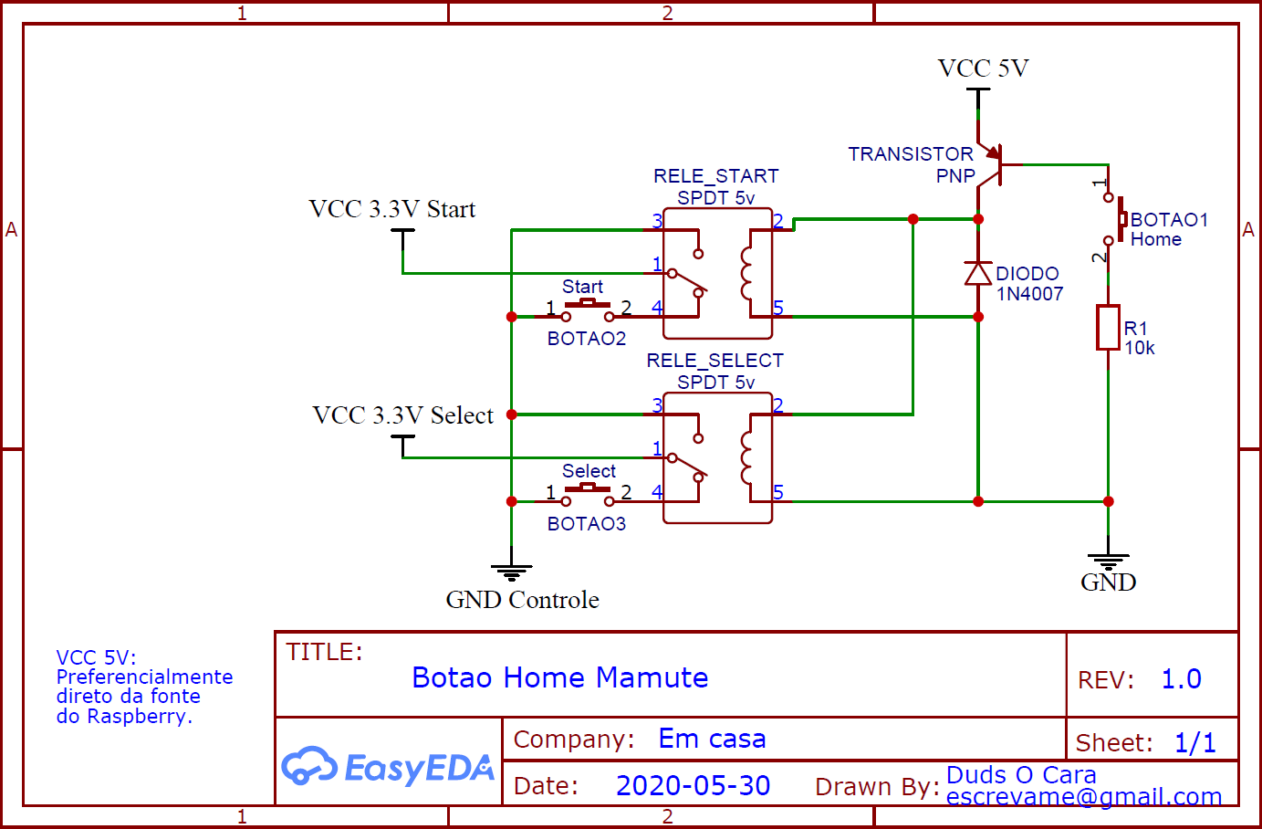
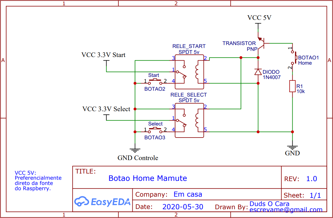
      Utilizei, além do botão Home, 2 relês SPDT 5V, um transistor PNP, um diodo 1N4007 e um resistor de 10k. A escolha dos componentes foi feita com base no que eu tinha aqui de resto, sobrando em casa, mas quem manjar de eletrônica consegue modificar o projeto e trocar os relês por outros transistores e deixar o projeto com custo de R$1 (cada relê custa aqui por volta de R$ 2,90 e cada transistor R$ 0,14). Mas enfim, quem quiser fazer igual ao meu, é só copiar o projeto.

      É desejável uma plaquinha universal de circuito impresso para soldar os componentes, no entanto, é possível soldar os componentes diretamente nos fios sem placa alguma ou utilizar um pedaço de papelão duro, caixa de fósforos daquelas Fiat Lux grande ou caixa de algum remédio; ou ainda uma plaquinha qualquer de madeira. A base não importa tanto desde que você consiga manter os componentes sem ficar encostando um no outro causando curtos.

      Eu fiz o projeto para o meu Raspberry Pi 3 B+ com Recalbox, utilizando os controles do Player 1 com o retorno à tela inicial com os botões Start e Select (hotkey) utilizando o chicote GPIO num gabinete de fliperama construído por eu mesmo. No entanto, esse esquema eletrônico funciona para qualquer tipo de controle (se precisar encolher o projeto pra controles pequenos ainda existe a opção de remodelar apenas com transistores).

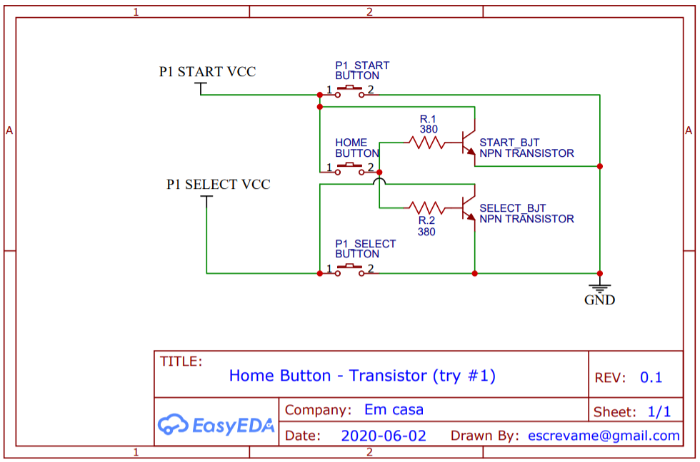
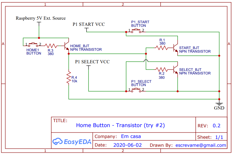
      Segue o diagrama esquemático:

      Botao-Home-Mamute-600x400_2020-05-31_19-26-44.png

      Na sequência, quem quiser simular o circuito, segue a validação do projeto no Tikercad:
      https://www.tinkercad.com/things/9ap3I2M21ws

      Vídeo: Circuito implementado na prática (funciona!)
      https://www.youtube.com/watch?v=FTBdr8fgu2A

      Vídeo: Mostrando o Botão Home funcionando em jogo
      https://www.youtube.com/watch?v=1hJHnYA5F_Q

      É isso ae povo! Abraços.

      posted in Controles / GPIO / Codificador USB
      Duds_O_Cara
      Duds_O_Cara
    • RE: configurar controles GPIO + USB para jogar 4 players ao mesmo tempo

      PS.: quanto aos jogos, vale o que o @Zing disse. Normalmente há roms do mesmo jogo com suporte 2p e 4p. Algumas até 3players.
      Abaixo o esquema da ligação no meu fliper.

      mamute_esquema_caixa_4p.jpg

      posted in Controles / GPIO / Codificador USB
      Duds_O_Cara
      Duds_O_Cara
    • RE: configurar controles GPIO + USB para jogar 4 players ao mesmo tempo

      Mano aqui eu instalei 2 GPIO e 2 via usb com placas zero delay. Uso também um quinto controle externo ao fliperama pra jogar bomberman de 5p.
      O resto Pra configurar foi automático, lembrando que hardwares iguais têm nomes iguais, então a função de botões que vc fizer num controle vale pra todos que compartilharem o mesmo hardware; mas essas configurações podem ser reajustadas dentro de cada emulador específico durante os jogos.
      Para jogos do snes é necessário habilitar o multitap dentro das configs do emu específico.

      posted in Controles / GPIO / Codificador USB
      Duds_O_Cara
      Duds_O_Cara